Fall 2018 Digital Lab 8

In this lab you’ll:

1) Make a multi channel MIDI drum sequencer.
2) Solidify your final project idea.

Part 1) Multi Channel Drum Sequencer

a) Start with your one channel drum sequencer from last week. Make sure it still works.

b) Add two buttons right next to each other, set their pin numbers nextChannelButtonPin and prevChannelButtonPin and set their pinModes. Make the one on the left the prevChannelButtonPin, and the one on the right the nextChannelButtonPin.

c) Add an int variable called channelDisplayed.

This variable should work exactly the same as the counter variable from the lecture homework from last week. You press the one button, its value goes down by one. You press the other button, its value goes up by one. If it’s value goes less than 0, set it back to 2. If it’s value goes above 2, set it to 0.

d) Replace your on[4] array with a multidimensional array containing 3 arrays, each of which has a length of 4.

boolean on[3][4] = {
  { LOW, HIGH, LOW, HIGH },
  { LOW, HIGH, HIGH, HIGH },
  { LOW, LOW, LOW, HIGH }
};

Think of each of the three arrays as a channel or instrument in your sequencer.

e) Anywhere you had on[someVariableOrNumber] replace it with on[0][someVariableOrNumber]. Upload and make sure it still works.

So right now you have a three channel sequencer, but you can only see and edit the first channel.

f) Use your two new buttons and channelDisplayed to control which of the three channels is being displayed on the LEDs.

It should still be sending the MIDI notes according to what’s on the first channel.

g) Update your code so that the channel currently displayed on the LEDs is also the one that controls your MIDI noteOns.

h) Make an array of 3 called midiNotes.

int midiNotes[3] = { 60, 62, 64 };

You can set the three numbers to whatever MIDI notes you want it to play.

i) Add one or more for loops to the part of your code that sends the MIDI notes to your DAW so that it will work with and play all three channels simultaneously.

As usual take a good clear video and include your code in your lab report.

I highly recommend in Arduino going to Edit -> Copy As HTML and using that you paste your code into WordPress rather than using  anymore since lately that seems to have all kinds of bugs in it and Copy As HTML seems to work way better.

Part 2) Start to finalize your Final Project

In class next week we will go around the room and everyone will share their Final Project idea. Be prepared to talk about your project for a minute or two at the start of class.
Lab 13 – Final Project Report

Final Assignment: Final Project Report

Next week’s class on 12/12 is our last class.  Next week in class you will be sharing your final project with everyone.

Your final assignment, due by next Friday, is your Final Project Documentation, which will be your final blog post for the semeseter.  It will consisting of the following:

1) At least one clear photo of your project.

2) An explanation of what your project is and what it does from a non technical perspective.  Think about this is as how you would explain your project to friends, family, students on the first day of this class next year, and random people on the internet without any knowledge of electronics.

3) A thorough technical explanation of how your project works in terms of code and circuits.  Imagine you are trying to explain it someone who wants to learn how your project actually works but hasn’t taken this class, or to yourself 3 months ago.  A schematic or diagram would also be helpful but is not required.

4) Your code, commented.

5) A clear, coherent video of your project working.  This should be at least 30 seconds long.  If you are the one demoing it, you must find a tripod or another person to do the camera work for you.  You may not hold your camera with one hand and demo your project with the other.  It must be 100% clear what’s happening in the video.

Lab 12 – Final Project Day 2

We’ll be working on Final Projects in class today.  You should do a lab report just like the one from last week with a status report.  On account of the holiday it’s due by midnight Monday 12/1, though it is in your best interest to get it done before then.

For students looking to make MIDI controllers I’ve added two tutorials on sending Midi from Teensy to Ableton Live.

Tutorial 1: Controlling MIDI Instruments with Ableton Live

Tutorial 2: Controlling Effects with MIDI Control Change Messages in Ableton Live

Timeline for rest of the semester:

12/5 – Final Project finished and working

12/12 – In class presentation and report on your Final Project due.

Your report will consist of an in depth documentation of your project, the code, the circuit, and will include a good 1+ minute video demo.

Controlling Effects with MIDI Control Change Messages in Ableton Live

This tutorial assumes you’ve gone through the Controlling MIDI Instruments with Ableton Live tutorial, and have successfully gotten MIDI communication working between Teensy and Ableton.

Part 1) Make sure Teensy is able to talk to Ableton

Make sure you have connectivity between Teensy and Ableton as described in Part 2 of Controlling MIDI Instruments with Ableton Live.

Part 2) The code

Take a look at the following code and upload it to your Teensy.  It uses one potentiometer, which you’ll need to wire up.

int pot1Val = 0;

int midiChannel = 3;

int controlChange1Val = 0;
int lastControlChange1Val = 0;

void setup() {
}

void loop() {

  lastControlChange1Val = controlChange1Val;
  pot1Val = analogRead(1);
  controlChange1Val = pot1Val/8;
  if(controlChange1Val != lastControlChange1Val) {
    usbMIDI.sendControlChange(1, controlChange1Val, midiChannel);
  }

  //its good to have some small delay in here
  delay(1);
}

Part 2) Add some audio.

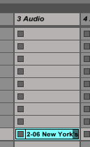
Drag an mp3 or other audio file from Finder or directly from iTunes into one of the Audio channels.

add audio

It will pop up in one of the rows and load itself into Ableton. Once its done uploading hit the spacebar and it should play. (It will stop when you hit it again).

Part 3) Add an effect

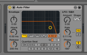
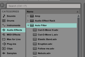
From the left menu select Audio Effects and then select an effect. I selected Auto Filter. If you haven’t used Ableton before you should probably pick Auto Filter too.

select audio effect

Click and drag Auto Filter or your other effect into the empty box on the bottom of Ableton that says “Drop Audio Effects Here”.  It’ll pop up with a bunch of options.

filter


Turn your potentiometer all the way off.

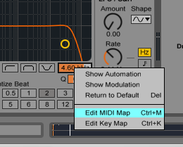
Right click the frequency cutoff parameter and select Edit MIDI Map.

editimidimap1

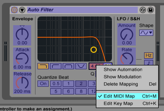
Turn the pot and the name of the parameter should suddenly pop up, along with the Channel and the Control Change number (under Note/Control) which you set in your code.  If you want to undo this mapping, just click and select it on the list and hit Delete.

midi mapping set

Now, go back to the effect, right click, and uncheck Edit MIDI Map.

deselect edit midi map

Everything should return to normal colors.  Turn your pot and you should see it changing the filter cutoff on the graph.

Hit space bar to turn on your music.  Your music should be plugged into your filter.

You can add as many more pots as you want, set them to different Control Change values, and then add more effects to Ableton and go through the same steps and add all of them.

If you’d like to use your effects to process the instrument you created in the other tutorial, on the Audio channel you where you added the effects set it’s Audio From: dropdown to your instrument.

Controlling MIDI Instruments with Ableton Live

Take a look at the following code and upload it to your Teensy. Note the button which will send the MIDI notes and wire it up.

Part 1) The code

int button1Pin = 12;
boolean button1Pressed = false;

int button1Note = 65;
int midiChannel = 3;
int midiVelocity = 127;

void setup() {
  pinMode(button1Pin, INPUT);
}

void loop() {
  if(digitalRead(button1Pin) == HIGH) {
    if(button1Pressed == false) {
      button1Pressed = true;
      usbMIDI.sendNoteOn(button1Note, midiVelocity, midiChannel);
    }
  }

  if(digitalRead(button1Pin) == LOW) {
    if(button1Pressed == true) {
      button1Pressed = false;
      usbMIDI.sendNoteOff(button1Note, 0, midiChannel);
    }
  }
}

Part 2) Enable MIDI from Teensy in Preferences

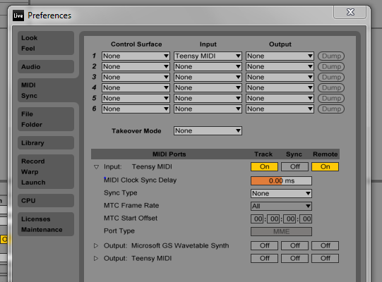
Open Ableton. Find the Preferences menu (In Windows it’s under Options > Preferences). It should open this popup:

preferences for midi

In the gray buttons on the left side click MIDI Sync.

On the top middle where you see a bunch of dropdowns under Input, click the first one and select Teensy MIDI.

In the middle where it says Input: Teensy MIDI, click the buttons directly to the right under Track and Remote so they’re turned on.

Close Preferences (it will save automatically).

3) Make your MIDI instrument

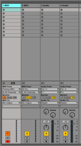
You should see 4 columns that look like this:

4 ableton instrument columns

These are “tracks” where you can create your instruments. Click on the top of the leftmost on on top where it says MIDI.

In the middle of that column, MIDI From: should be set to Teensy MIDI.  The dropdown underneath that can be either All Channels (if you’re just using one channel for your project), or the MIDI Channel you set in your code.   Monitor should be set in In.

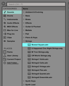
All the way on the left side of your screen you should see CATEGORIES.

categories

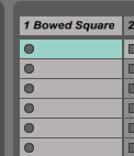
Click Sounds and then select an instrument/sound from the options.  Decide whichever one you want and then click and drag in onto the column of the track you set up.  The top part, which said MIDI a second ago, should now be titled with whatever instrument you chose.  I chose “Bowed Square” as you can see below.

track with instrument

Try it! Your instrument should play.

Quick Multiplexer Lesson

Please create the following circuit and post a 10 second video clip of it working on your blog. You have until the end of the semester to do this.

A multiplexer allows you to route a single signal or voltage to a large number of different output channels, or to route a large number of inputs into a single input channel.

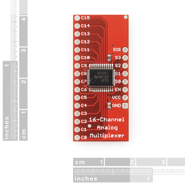
Take a look at your multiplexer (or, the photo of it above).  On the right side you’ll see pins SIG, S0, S1, S2, and S3.  On the left side you’ll see C0 through C15.

Connect VCC to power.
Connect EN and GND to Ground.
Connect S0 to digital pin 2.  S1 to digital pin 3.  S2 to digital pin 4. S3 to digital pin 5.
Connect SIG to whatever resistor you normally use for an LED and connect the other end of it to power.
Connect C0, C1, C2, and C3 to LEDs to ground.

Upload this code:

int controlPins[] = {2,3,4,5};

void setup() {
  for(int i=0; i<4; i++) {
    pinMode(controlPins[i], OUTPUT);
  }
}

void loop() {
  for(int i=0; i<4; i++) {
    routeSignalToPin(i);
    delay(500);
  }
}

void routeSignalToPin(int pinNum) {

  for(int j=0; j<4; j++) {
    digitalWrite(controlPins[j], (pinNum >> j) & 1);
  }
}

It should turn on the 4 LEDs one at a time.

How it works.

SIG is the signal you want to route – it can be audio, MIDI, Serial data, or just a set, unmoving voltage.  Really anything, so long as its about 5 volts or less.
S0, S1, S2, and S3 are the select pins.  You connect these 4 pins to 4 digital pins on your microcontroller, and depending on which ones you set HIGH and LOW, it will connect the SIG pin to one of the 16 output pins C0 to C15.

Think of S0 to S3 as the 4 bits of a 4 bit number.  As you know, a 4 bit number can be from 0 to 15.  S0 represents the first bit, S1 represents the second bit, s2 the third bit, and s3 the fourth bit.

Say you want to route your signal (whatever you’ve connected to the SIG pin) to pin C11.  To set this you need to know the binary, 4 bit number for 11.  This number in binary is 1011.

If the first bit (the 1 in 1011) is a 1, you digitalWrite the Teensy pin connected to S0 HIGH.  If it’s a 0 you set it LOW.
If the second bit (the 1 from 1011) is a 1, you digitalWrite the Teensy pin connected to S1 HIGH.  If it’s a 0 you set it LOW.
Third bit is a 0 (1011), so, you digitalWrite the pin S2 connected to LOW.
You hopefully can guess what you do with S3 and the fourth bit (1011).

And that’s how it works.  You set S0 to S3 with digitalWrite()s, and it controls which of the 16 channels C0 to C15 is currently connected to SIG.  You can also connect pots or switches on any of the 16 different channels, and use SIG as a digital or analog input into your microcontroller and doing the standard digitalRead or analogRead on it.

Lab 11 – Final Project Day 1

In class today we’ll go over and work on finalizing your projects.

Your Final Projects are due on the last day of class. In addition to building the project you will have to document extensively how it works and make a good clear demo video. The idea is to document your project in such a way that someone else with less experience than you could understand and build it. The specific guidelines on what you need to do will be set in stone by next Friday.

For next weeks lab report, make some progress. Put a big dent in the work of your final project and document what you’ve done:

1) Explain again in at least a few sentences what your final project is.
2) Explain what you’ve done so far.
a) Make a short, but clear video documenting some great or small aspect of your project working beyond what you’ve already done in previous labs.
b) Include your code with comments as necessary.
c) Explain what you have left to do and how you could organize your time between now and the last day of class.

Lab 10 – Sensors and Mapping Values

In this lab you’ll:

1) Learn to use an analog sensor as an analog input into your microcontroller and use it to control an output.

Part 1)

In your Beginner Parts Kit you should have one photo cell.  This is a light sensor – it’s resistance changes based on how much light is shining on it.  More light, less resistance.  Plug one end of it into one of your Teensy’s analog inputs, and the other end into power.  Then plug a 1k resistor from that analog pin into ground.  Make sure Tools > USB Type is set to Serial and Tools > CPU Speed is something 24 or greater. Upload this code:

int sensorVal = 0;
int mappedSensorVal = 0;

void setup() {
  Serial.begin(9600);
}

void loop() {
  sensorVal = analogRead(0);
  delay(10);
  Serial.println(sensorVal);  
}

Open the Serial Monitor (Tools > Serial Monitor). Wave your hand around in front of the sensor. Make note of the biggest and smallest values you see.

Now you want to use your photo cell to accurately control… something, but the values you get directly from the photo cell aren’t exactly what you want. Say you wanted to use this to control one of our digital pots, whose value is controlled with numbers between 0 and 127. You will need to use the map() function. Say your photocell gives you numbers between 12 and 297.

mappedSensorVal = map(sensorVal, 12, 297, 0, 127);

will take your sensor values between 12 and 297 and convert them into numbers from 0 to 127. Replace those with your own min and max values. Try removing the Serial.println(sensorVal) above and instead serial print mappedSensorVal to see it working.

Part 2) Use it.

Integrate this with any of the squarewave synth tone generating code we’ve done in class before, so that the sensor will control a tone that can glide from two octaves below middle C to one octave above middle C. It’s not mandatory but if you really want, I’d encourage you to implement it with a digital pot as well.

Part 3) Final Project.

We’ll be mostly working on your final projects in class from here on out. Decide on what you’re doing and come prepared to spend a minute explaining it in class next week. In the meantime ask me for any advice you need.

In your lab report give a good explanation of your project that would be clear to me or anyone else in class reading it. If a drawing or diagram would help, by all means include that as well.

Include a list of all parts you’ll need for your project and whether you have them already or not.

Lab 9 – Step Sequencer

In this lab you’ll:

1) Make a simple melodic step sequencer.
2) Add some interesting and useful features to it.

Part 1) Basics.

Take a look at this code, figure out what you need to plug in where on your microcontroller, and upload.  This IntervalTimer oscTimer and the playNote() function have been set up in such a way  that you can play any frequency without worrying about the effect of delays or anything else.

1a) Take a look at playNote() and see if you can make some sense of it and explain how it works in your lab report (feel free to skip this part during class so you can get to the more interesting stuff in part 2).  Keep in mind oscTimer.begin(playNote, 1); essentially means: do playNote() every 1 microsecond.

Part 2) Now make a better sequencer:

a) Add a tempo knob that controls the step speed.
b) Make it a 4 step sequencer (or more, if you really want).
c) Make it so that if you press a button, the whole sequence plays backwards.
d) Figure out how to use the random() function, and make it so that if you press a different button the sequencer will go to a random step every time, rather than in order.

Part 3) What else can you do with a sequencer?

a) Imagine you wanted to make a more advanced sequencer for your Final Project.  Explain 4 different features you could, with enough time and effort, foreseeably add to this sequencer to make it more interesting based on what you’ve learned so far this semester.
b) Explain one or two features which would be nice to add to your sequencer, but which you don’t think you could do with the skills you’ve learned thus far.